Master Blaster Glasspacks
with Silencers à la Mark T
|
||
Parts/material required:OEM exhaust system |
||
Tools required:Bubble level |
Note: Click on any image to view the full size picture. |
|
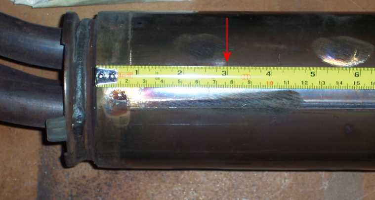
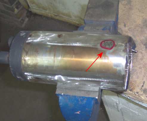
Make a Mark 3 inches from the Header EntryThe front portion of the exhaust can will
be used to attach the collector/reducer.If you look at the can you will see spot welds that are approximately
3 inches from the forward edge. These are used to secure dividers inside
the can. These dividers section As shown by the arrow in the picture, measure and mark the can approximately 3 inches back from its forward edge (where the header pipes enter). |
 |
|
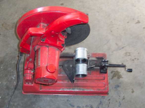
Cut on Mark with Chop SawIf using a chopsaw, just cut through the whole
thing. Note: At the front of the exhaust can, there
are two tabs on each side with rubber |
 |
|
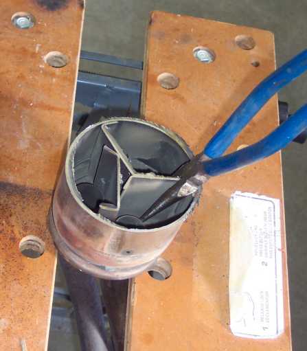
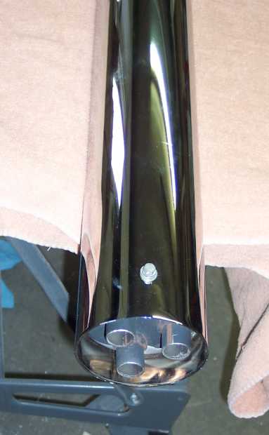
Pull Out SeparatorsAs mentioned above, the inside separators
are only spot welded in one place at the front Since these are not welded to the bottom of the can, cutting through the spot welds will permit easy removal of the separators with pliers, vice grips, etc. Pull these three little separators out and discard. |
 |
|
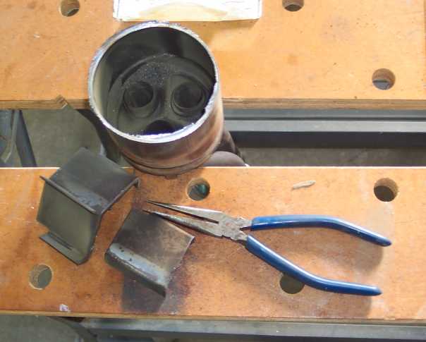
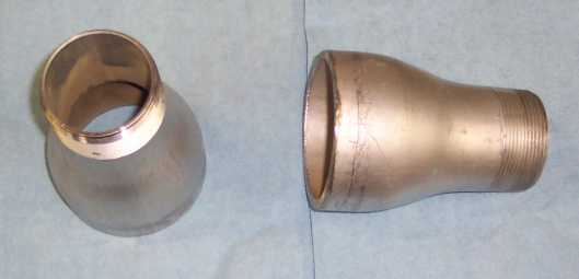
Exhaust Can Without SeparatorsOnce the separators have been pulled out, the can is ready to receive the collector/reducer.
|
 |
|
Swage Nipple Collectors/ReducersThese swage bell reducers, which have been
"discovered" by Master Blaster, work very well. Note: These swage nipples, which are usually
8 inches long, are now only 5 inches long. A search on the web for swage fittings indicated
that these can be purchased at: |
 |
|
Set Header Vertical and LevelNote: You need to use a small bubble level to make sure everything lines up before welding. Clamp the header straight up and use a level
on a few sides of the can to ensure that the |
 |
|
Set Swage Nipple Square With CanSet the swage nipple in the can (make sure that it is flat on the bottom of the can). Notes:
Note: The nipples will not be welded to the bottom of the can but inside the outer rim. |
 |
|
Set Swage Nipple Square With Can
|
 |
|
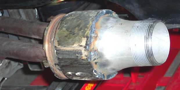
Weld the Collector to the HeadersHeat a rod about 5/16 in diameter and wrap
around the neck of the nipple on the inside of the exhaust can . |
 |
|
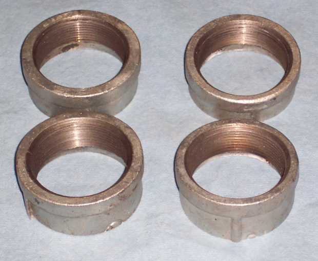
Threaded connectorsCommon 2-inch water pipe connectors can be
used to connect the mufflers and straight pipes to the swage collectors.
|
 |
|
Cutting the Threaded Connectors with a Chop Saw |
 |
|
Two Sets of ConnectorsYou will note that the inside diameter of the threaded portion is smaller than the inside diameter of the body behind the threads. Since the smooth body portion of the connectors are a little larger than the muffler necks, you can use a ball peen hammer to bell out the muffler necks in order to ensure a tight fit. A smooth exhaust flow will then be obtained because the end of the pipe will be behind the threads on the connector. Slip these connectors over the neck of the muffler and, before welding, use the level again to make sure they are square.
|
 |
|
Cut Silencers From Rear of CanIn order to make insertable silencers from the back baffle section of the exhaust, locate the rearmost spot welds. Cut just upstream of these rearmost weld(s). These cut will be approximately 7 1/8 inches from the rear of the exhaust. Note: Those 3 spot welds hold the rear baffle dividers inside the can. |
 |
|
Cut Piggies From Rear of Silencers |
 |
|
Grind Away 3 Separator Spot WeldsIn order to remove the 3 separators at the front of your silencers, grind away the 3 retaining spot welds. |
 |
|
Remove SeparatorsThe separators can now be twisted out with a pair of pliers. |
 |
|
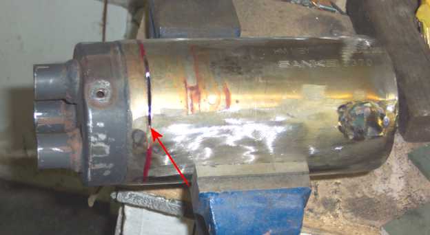
Peeling the Silencers: Circular CutIn order for the silencers to fit freely within the commonly sold 4-inch truck stacks, the exterior skin must be taken off. A cutting wheel on a grinder can be used (with care) to cut the exterior skin off the silencer at the location shown by the arrow. Note: Do not cut any deeper than the thickness of the skin. Otherwise the baffles will be damaged (i.e.: the silencer will be ruined). You will note that there are also spot welds on the "piggie end" of the silencers. These must not be destroyed because they are needed to support the baffles. Cut approximately ½ inch (toward the middle of the silencer) away from that spot weld. |
 |
|
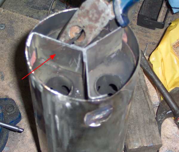
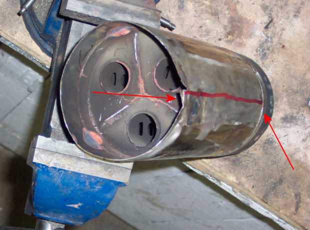
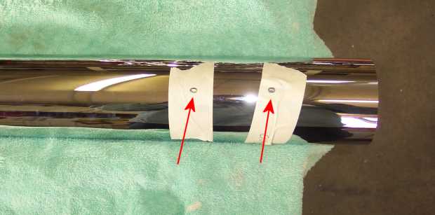
Peeling the Silencers: Horizontal CutIf you look at the front end of your silencer, you will note that each baffle is separated by a thin wall. Each baffle and adjacent separating wall must be kept intact. In order to do so, make a mark between a baffle and one of its adjacent little separating walls, and then cut along that mark.. See the red arrows and cutting line in the picture. |
 |
|
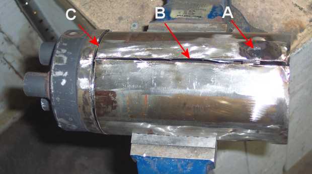
Silencer Ready to be PeeledThe spot welds (A) have been ground away, the circular (C) and horizontal (B) cuts have been completed. |
 |
|
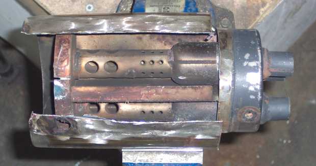
Peeling the SilencerIt is now quite easy to peel the skin off with a pair of pliers, vice grips, etc. |
 |
|
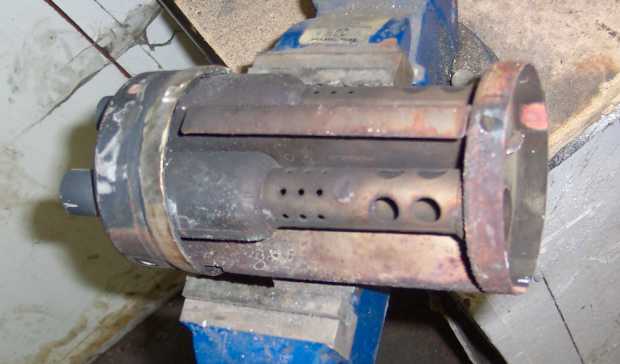
Silencer Ready to be InstalledIt may not look fancy, but it functions very well. |
 |
|
Tightly StackedIf your stacks fit too tightly, you will need to drive them on , and they will be a real problem to get off later on down the road. I know of two solutions (other than waiting
to find a stack that fits freely): |
 |
|
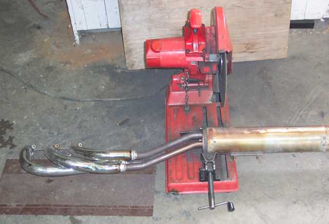
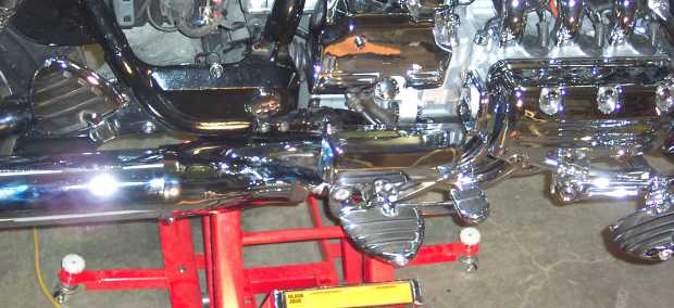
Different Components on the FloorA = Header and front portion of the can |
|
|
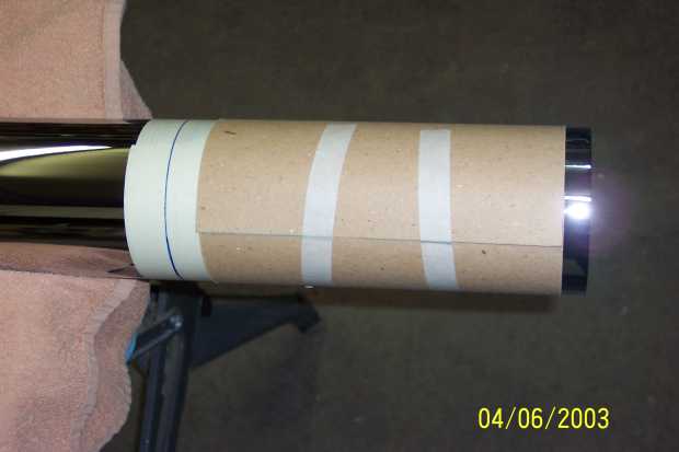
Measure and Mark the Stacks for CuttingAfter wrapping the stack with masking tape at the approximate cutting location, a piece of cardboard wrapped around the stack permitted me to make a straight mark around the stack at the cutting location. I have chosen to cut the stacks at 38 inches.. |
 |
|
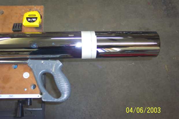
Cut the StacksI have used a 24 TPI (teeth per inch) blade on my hacksaw in order to cut 48-inch stacks down to 38 inches. Note: The cut was then filed and touched up with high temperature aluminum paint. |
 |
|
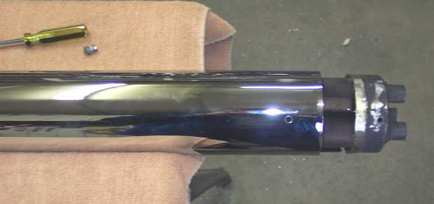
Place Silencer in Stack, Mark and DrillSince each silencer used to be the rear baffle portion in the OEM system, it already had 2 threaded openings to secure it to the muffler. Place the silencer where you would like to install it within the rear portion of the stack, and mark the location to be drilled. Once drilled, it will be very easy to fasten the silencer to the stack. Note: Use the bolts from OEM exhaust. One bolt per silencer is enough. |
 |
|
Silencer Fastened Within Stack |
 |
|
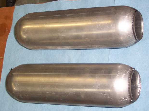
Types of GlasspacksSome mufflers come as blanks with no inlet/outlet
pipes attached. Some come with the inlet /outlet pipes attached. If your mufflers are the blank type, you will
need to weld on the short extensions. Mine were blanks, such as shown
in the picture. However next time I will purchase them with inlet and
outlet pipes attached. It will make things easier. Master Blaster mentioned that he uses two
types of 12-inch long mufflers (usually purchased from JC Whitney). One
has a 3 1/2 inch case with a 2 inch core. The other has a 3 inch case
with a 1 3/4 inch core. |
 |
|
Assembling the GlasspacksIf your mufflers are blanks, you will need to weld a 3-inch neck on each end (i.e.: inlet and outlet). The front neck is required to prevent the shoulder of the muffler body from being in contact with the bolts used to mount the truck stack to the bike frame. The rear neck is required by the swap out tool. You will see this tool later on below. Lay each muffler body in a channel and level
it. Then put the level across the threaded end of the connector in all
directions to level it. Note: You need to make sure that these necks are made of 2-inch inside diameter exhaust pipe The removal tool will be made out of 2 inch outside diameter exhaust pipe. It needs to be able to slip into the necks and not be too loose a fit. |
||
Fin Direction Within the GlasspacksIf you look inside a glasspack muffler, you will notice fins (little cups) pointing towards the front in order to catch some of the exhaust. Thus the sound will be muffled. I have chosen to flip the glasspack around in order to let the exhaust flow over these little fins, instead of into them. This gives the exhaust system a more "attitude". |
||
Fabricating the StraightsThe straights are fabricated the same way
as the mufflers. |
||
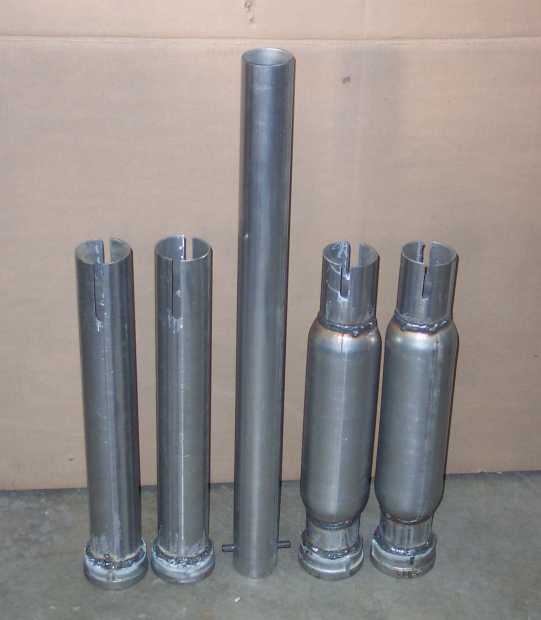
Glasspack Swapout ToolFor a tool to swap them out with, you can
use a piece of 2-inch exhaust pipe 18 inches long and drill a 5/16 hole
about 1 inch back on each side 180 degrees out. Note: The picture shows straight pipes on the left, the swapout tool in the middle, and the packs on the right hand side. |
 |
|
Anti Seize:You have to use anti seize on the threads
or they will freeze together. Note: Liberally use anti-seize, change them on a weekly basis, and they will work fine. |
||
Mark Position of Front CoversIn order to obtain a smooth flow of chrome
front to back without the seam that shows on the stock setup, the stack
should slip about ¼ inch under the front chrome cover that is over
the header pipes. As shown in the picture, I have installed the front cover and marked the location of its edge on the exhaust can. After removing the front cover, another mark was made ¼ inch ahead of the cover mark. This will be the location of the front edge of the stacks
|
 |
|
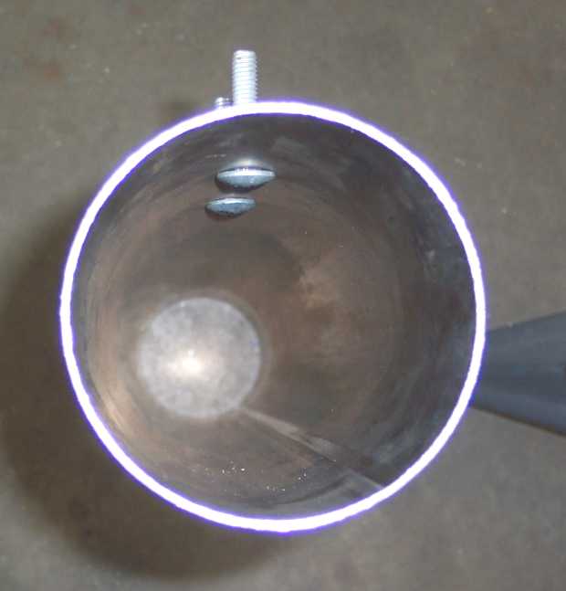
Mark the Stacks for DrillingSlip the truck stack over the can. Position
the front edge of the stack on the mark that has been made on the can
in the previous step. Remove the stack and drill two 3/8-inch holes where you have marked it. |
 |
|
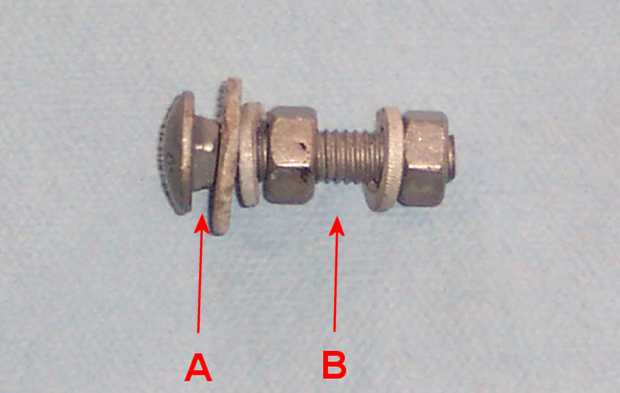
Galvanized 1¼ inch X 5/16 Carriage Bolts (with nuts, flat washers and lock washers)To mount the truck stacks, round headed galvanized
1¼-inch X 5/16 inch carriage bolts (along with galvanized nuts,
washers, etc.) have been used.
|
 |
|
Bolt Heads Inside the StacksPut in the carriage bolts with a washer, lock washer, and nut. Tighten them until the heads of the bolts fit flush inside the stack. Note: In order for the round headed carriage bolts to mount the stacks to the hangers, 3/8-inch holes were drilled into the stacks. Since these holes are slightly smaller than the little square portion of the bolt, when the carriage bolts are tightened down, the little square is force fit through the hole. This prevents the bolts from turning while being tightened. |
 |
|
Bolts Outside the StacksThis is how the bolts sticking out of the stacks will mount into the frame. |
 |
|
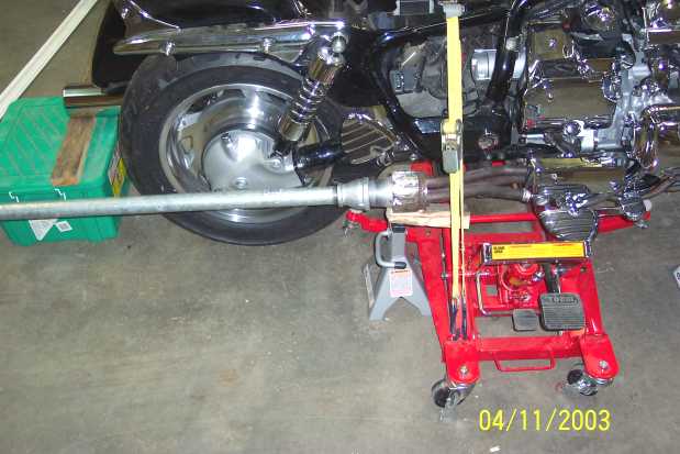
Glasspack Tweak ToolIf the swage fittings have been welded perfectly
level within the cans, and if the connectors have also been perfectly
lined up with the mufflers and straight pipes, everything (stacks included)
will line up perfectly. |
 |
|
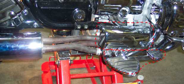
Fitting the Cover Over the Right StackThe front chrome cover is relatively easy to install over the left stack. However it's a bit more difficult on the right side. As shown in the picture, the brake pedal, the foot peg and a cover just above these are in the way.
|
 |
|
Wire to Clear the PipesRemove the chrome cover and then remove the
two bolts that hold the whole brake assembly to the frame.
|
 |
|
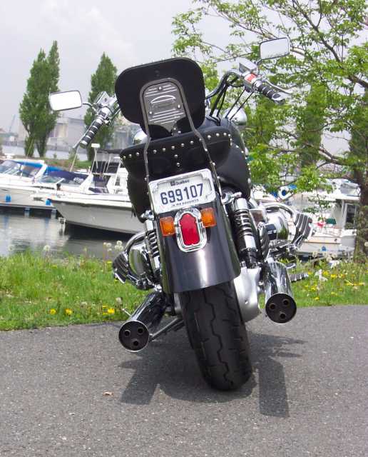
Chrome Is Good for You!There is now a nice smooth flow of chrome front to back without the seam that shows on the stock setup. |
 |
|
  |
|
 |
Sound Files: |
|
|
| nice mellow sound | 10-inch Glasspack | |
| Glasspack + Silencer | ||
| louder with a bark in it | Straight Pipes | |
|
Straight Pipes + Silencer |
||
| very loud deep roar | Swage Collector only | |
| Swage Collector only + Silencer | ||
|
Hats off to Master Blaster for patiently explaining each step (many times) of his glasspack system and also a special thanks to MarkT for coming up with the silencer idea. |
||