Honda Valkyrie Alternator Service
(Standard/Tourer Shown)
Thanks to "Ratdog" for this how to page.
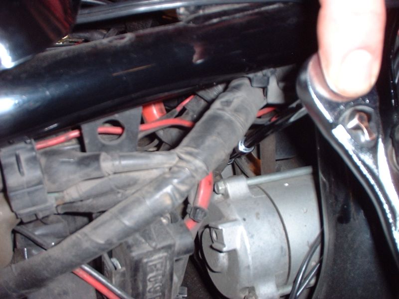
Removal: After disconnecting the battery, I pulled the right side cover and used a long ¼” drive extension to access the 10mm nut (holding the cable to the alternator). I have a magnet insert in the socket (Craftsman) to help keep track of the loosened nut.
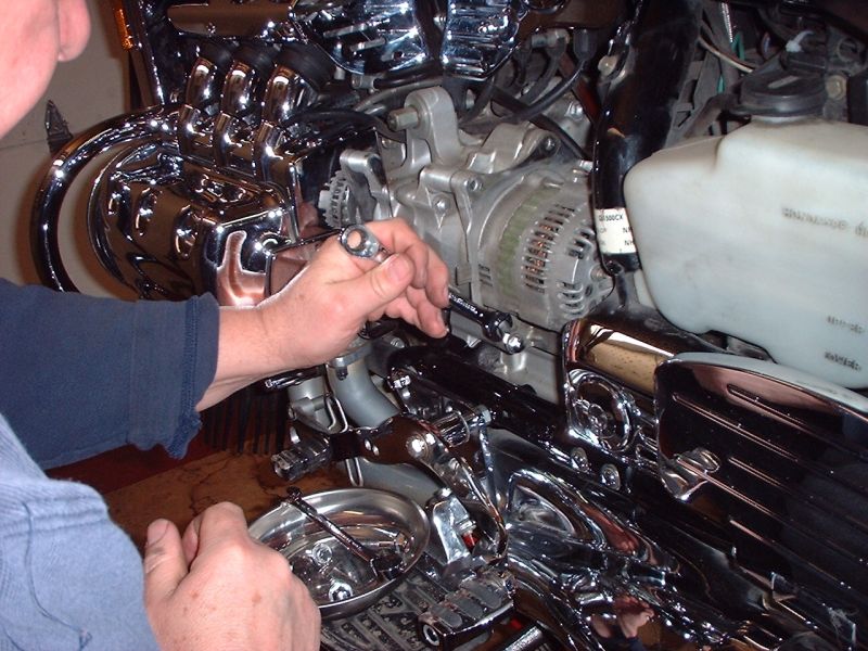
Removal: From the left side of the bike, once you’ve gained access to the alternator, unbolt the alternator from the case. Pay attention to the location of the bracket that’s going to come free. You’ll also need to free the path of the alternator’s removal (electrical, as well as drain line) from two places. (Between the alternator and engine case, as well as between the rear portion of the alternator and the frame member.) At some point in time you’ll also need to disconnect another wire from the alternator before removing it altogether.
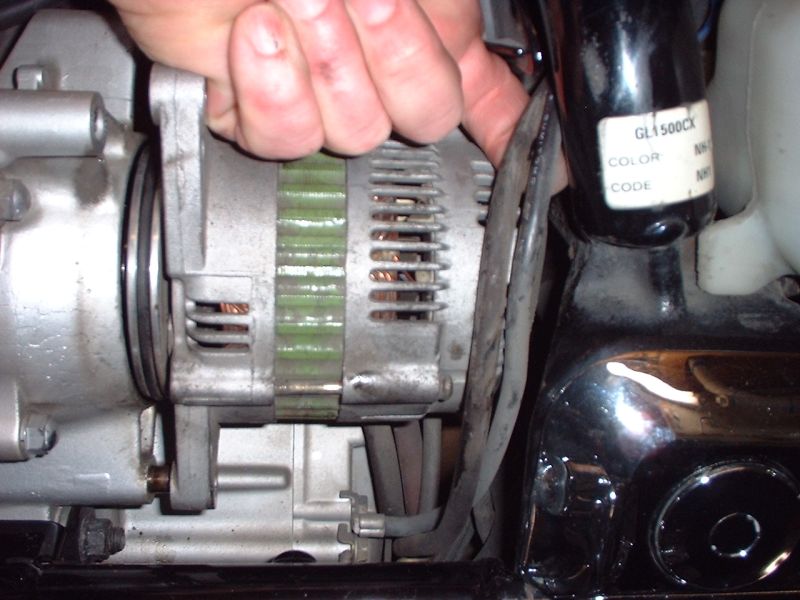
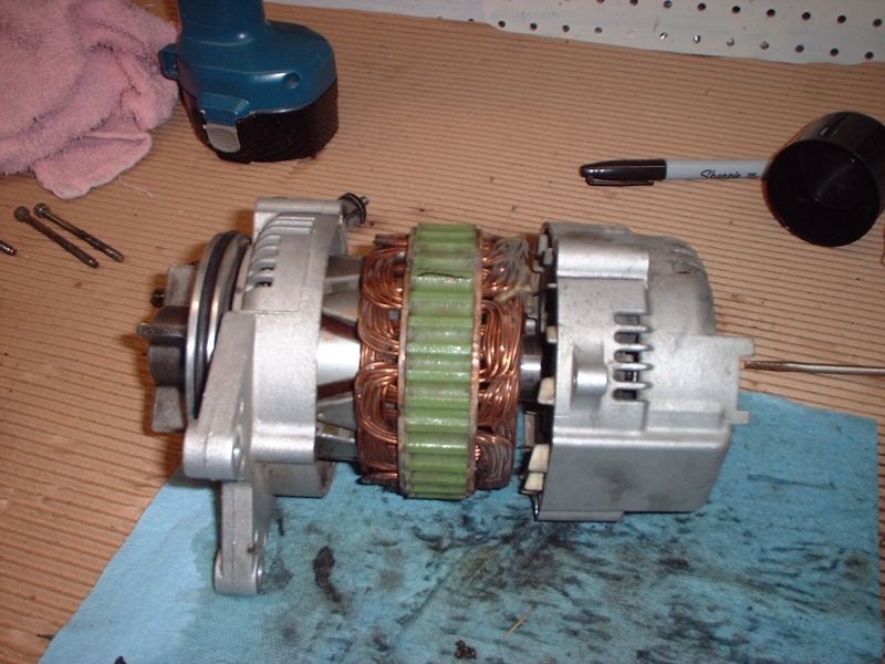
As you can see above, you’re ready to pry the unit loose from the drive assembly (inside). This will allow you to work it loose as you pull rearward, push the back “inward” (towards the centerline of the bike), and work the nose (front) outward until it’s free of the drive assembly. Two things: The lower/right area (as you look at it) will want to bind against the frame member as you work it free. Once you overcome that, the metal fins will divorce from the rubber dampers inside the drive assembly. You’ll see a little oil present (that’s normal). You may need to rotate the assembly a bit to get it worked free.
Scribe the Housing: Before separating the alternator, scribe the housing sections (three) so that you have an orientation of which is the correct way it goes back together. Note… if you use a marking pen, the ink may be washed away when using some spray electrical cleaner. I used the pen for visual reference. A scratch awl will probably do a little better.
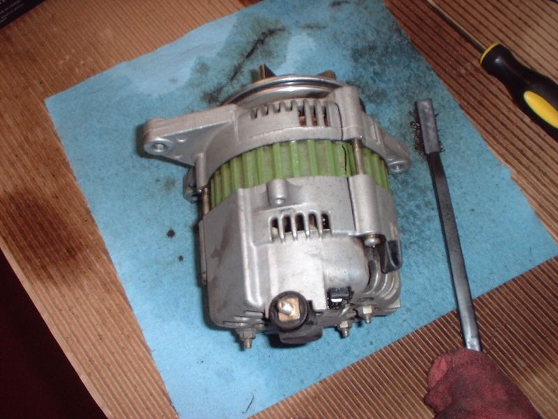
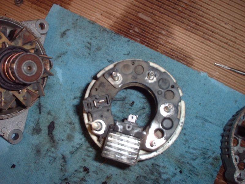
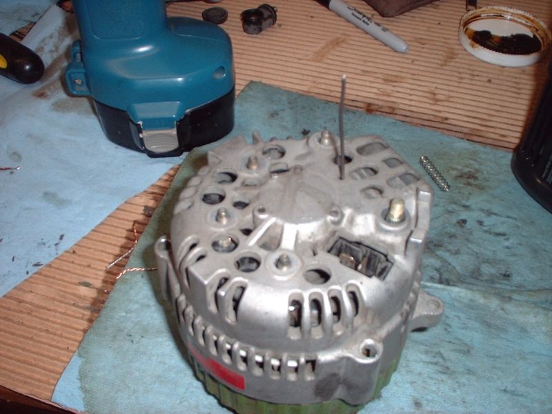
Separation: A narrow, slotted screwdriver works well for getting in to separate the three sections to pull it apart. You must first remove the nuts shown in the above picture, as well as the three long screws, which keep the sections secured together. Pay attention to the location of pieces as you remove them… as well as how they sit.
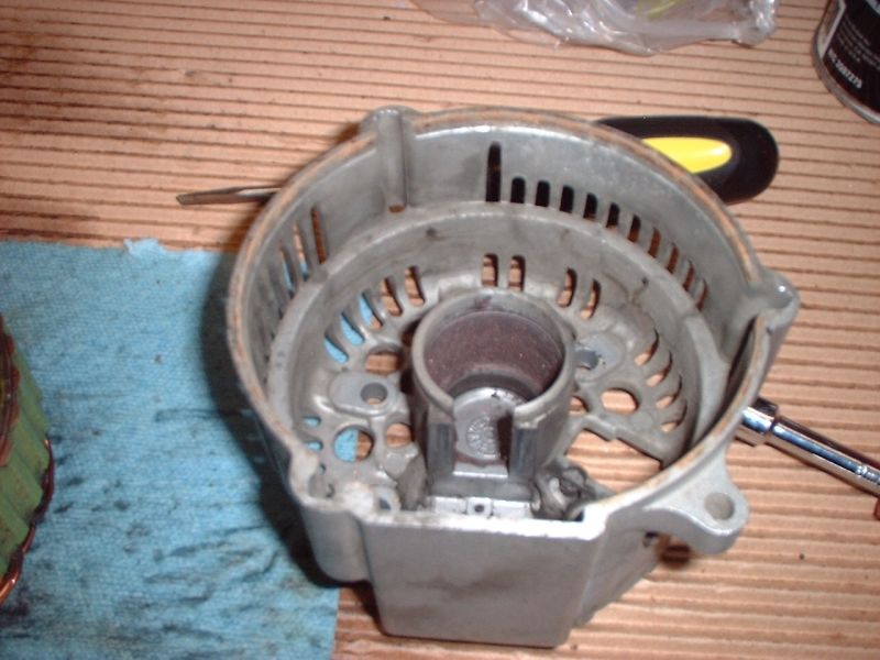
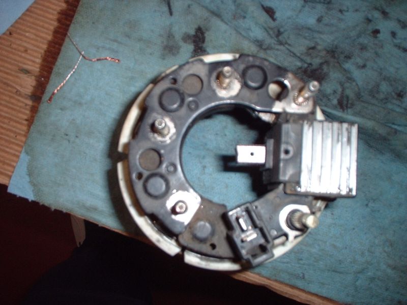
Clean Up: Now is the time to begin cleaning the residual dust from the wearing brushes from inside the housing, as well as from the windings. Some compressed air and aerosol electrical parts cleaner will do good things. As you can see below, there’s no place for the residual dust to go, so it just hangs around inside the housing
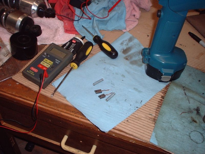
Brush Inspection: This is what mine looked like after 80,000 miles. At 40,000 I did an inspection/cleaning. I’m a firm believer in pulling/inspecting/cleaning them every 40,000 miles. That dust won’t do good things if left in there for a long period of time. The brushes will have a notch scribed into them. If the notch is extended beyond the housing, it’s time to replace them. They’re cheap, about $8.00/pair from Honda. You will see a hole in each brush. Push the brush in (against the spring tension) and you’ll see a hole in the housing, which lines up with the hole in the brushes. If you need only to do an inspection/cleaning, then depress the brushes and use a paperclip (inserted through the housing) (detailed later) to hold the brushes in this “cocked” position before assembly. If it’s time to replace them, make mental note of the direction of the “lay” of the arc on the brush… or the side the wear indicator scribe faces on the brushes.
This pic (below) illustrates how to “cock” the brushes into place using the paperclip.
Brush Replacement: You’ll find two solder spots on the housing that hold the wound copper tails of the brushes. As you melt those with your iron, be ready for them to pop loose. The springs shown below have the tails threaded through them and keep the brushes pushing out as they wear.
New Brushes: Paying attention to the orientation of the scribe mark on the brushes as you’re replacing with new ones… here’s what you’re going to need to accomplish. First, thread the tails through the springs and the task is to fish the tails through and out the holes in the housing. If you’re like me… a little tension on the tail and a dab of solder to give the tail some rigidity will make life a little easier. Just remember that you don’t want a glob of it big enough to hinder your ability to thread the tail through the hole.
Next thing is… You want to have the new brushes pushed in JUST FAR ENOUGH to replicate the distance they extended before you removed the old ones. So… pay attention to how far they were. With them pushed in to that distance, it’s time to solder the tails to the housing, and trim the tails afterwards.
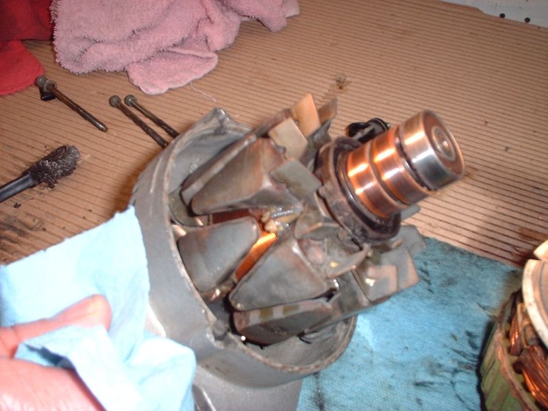
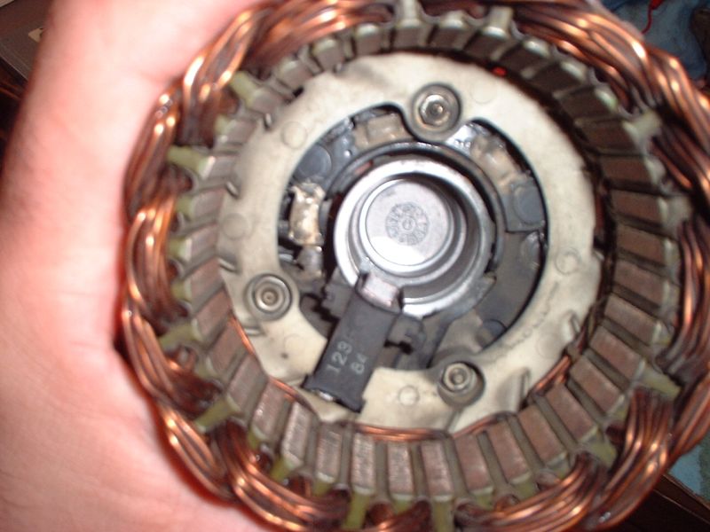
More cleaning: Below… you see the bearing (silver) and the surfaces (copper) your brushes ride on. More cleaning of this entire assembly with compressed air and aerosol electrical parts cleaner will give you a little more clear picture of the condition of things. I found some scores in the copper, but nothing alarming. Everything had been working just fine, so I wasn’t concerned with a major overhaul of the internals. I am detailing the inspection/cleaning/brush replacement here.
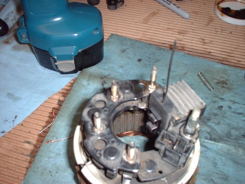
Assembly: Below, you can see that as I’m putting the sections back together, I’ve inserted the paperclip through the outer housing, as well as the holes in the installed (new) brushes, this holds them in their “cocked” position.
Below, you can see the cleaned assembly from the inside. The brushes are cocked and ready to marry with the third section.
Once the third section is married, pull the paperclip and reassemble the pieces you removed before taking it all apart. A little bit of assembly lube/anti-seize to the threads will make life easy the next time you take things apart.
Putting everything back together is basically a reverse order of taking the alternator out. A little lube on that big O-ring won’t hurt as you’re marrying the metal fins into the rubber dampers again. Keep those lines/wires out of the way as best you can to ease the process of putting it all back together again. If you get rough with it, you MAY end up disconnecting the drain tube from its “T” (above the alternator’s location). Just pay attention to what you’re doing.