Desmog
Submitted by
QueXpress (Normand in QUÉBEC)
Disclaimer
Information has been provided
on these pages in hope that it will be useful.
Each of these pages contains steps followed to complete certain modifications
on my bike.
This is not a shop manual. I am not a mechanic.
I assume no liability for any damages, direct or otherwise, resulting
from the use of this information.
If you choose to follow the steps on these pages, you do so AT
YOUR OWN RISK.
Our Valks have been equipped
with a secondary air supply system in order to reduce engine emissions
.
Whenever there is a negative pressure pulse in the exhaust system (i.e.:
when you close the throttle), fresh air is drawn into the exhaust port
in order to promote burning of unburned exhaust gases.
This is fine until you experience an increase in rapid, annoying, popping/gurgling
sounds when throttling down. With aftermarket exhaust systems, glass pack
mods, etc., lower backpressure seems to make this annoyance even worse.
A permanent fix to this is the removal of the PAIR (Pulse
Secondary AIR Injection) system as shown below.
The fuel mileage, power or general engine running will not be affected
by this mod. However clutter on the engine and also annoying snap, crackle
and pops will be history.
Note: Click on any image to view the full size picture.
Attribution:
This mod was made possible with the help of many guys on the VRCC tech board (in this case, especially Mase, Patrick, Þrúðr and Slammer). The following is based and has been inspired by the excellent write ups of Lamonster and also of Tim Skelton.
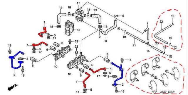
Parts to be Removed:
Everything shown in the diagram is to be removed except the intakes (encircled in red) and the petcock vacuum tube (also encircled).
Note: The red air feed pipes can be accessed on top of the engine, and the 2 blue ones under the engine.
Parts required :
5/32 Vacuum plugs for intakes 3 and 4
Four 14 mm freeze plugs (not necessary if you choose to use existing parts as explained below)
2 gaskets (part number 17142-MN5-000): not mandatory (the old ones could have been kept)
I have made up 2 small aluminum plates as shown (not necessary if using existing parts as explained below)

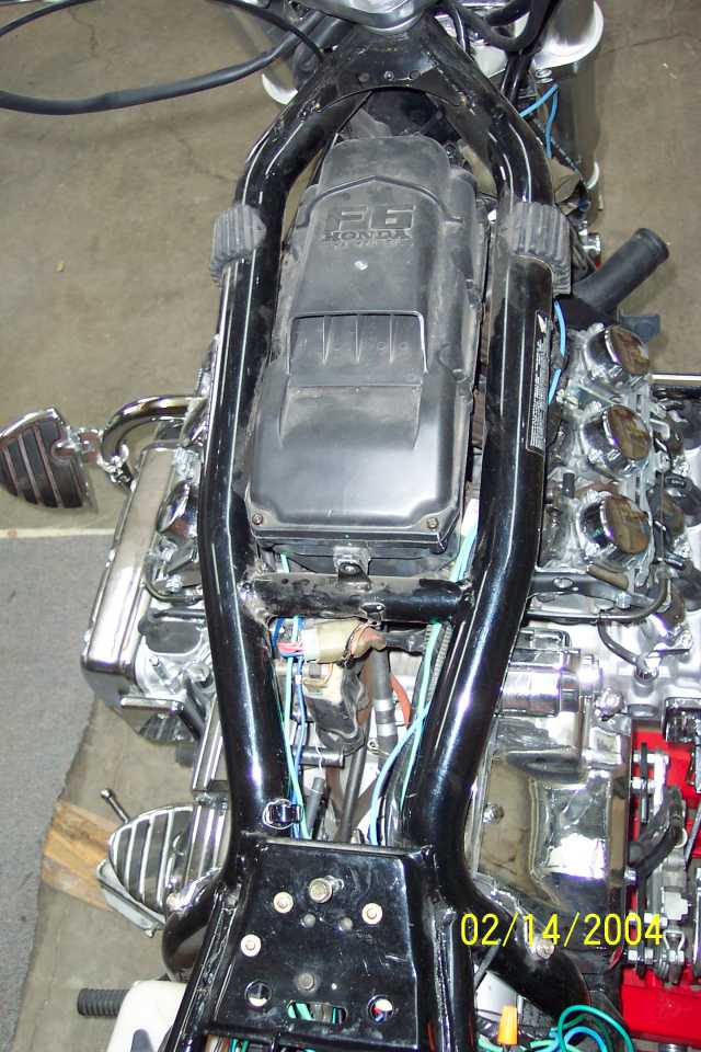
Remove Fuel Tank, Then the Airbox
In order to get at the PAIR control valve
and also the two PAIR check valves, the fuel tank, followed by the airbox,
must be removed.
Remove the PAIR control valve assembly and also the 2 attached vacuum tubes going to intakes 3 and 4.
Block off the vents on the intakes for carbs 3 and 4 with 5/32 vacuum plugs.

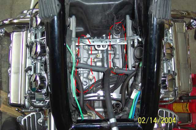
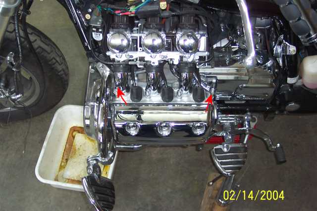
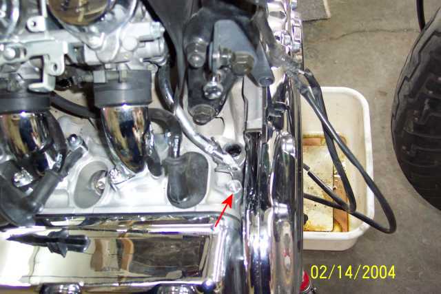
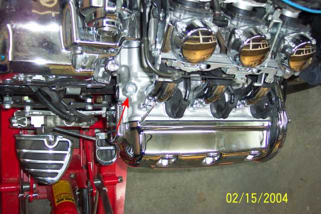
On the left side of the engine, 2 air feed pipes (going to exhaust ports 2 and 6) can be removed from the top.
Note: removal of the air feed pipe to exhaust port 4 will be done under the engine (see next pic).
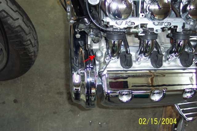
View of the air feed pipe under the engine
on the left side.
Note: I found it easier to work with the exhaust header removed.
Note: After removal, I have used a small aluminum
plate and a gasket (shown in the Parts Required above).
Others choose to cut off the end, fill it with JB Weld, and wait until
the next day before reinstalling with a gasket.
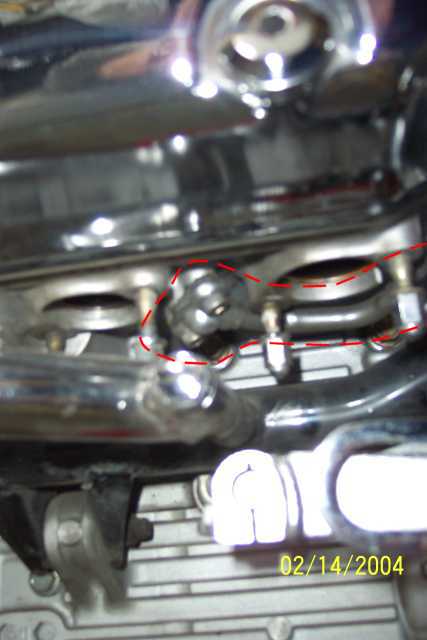

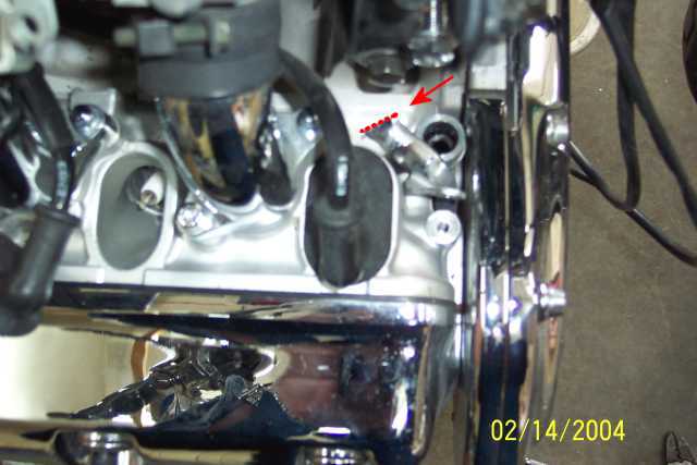
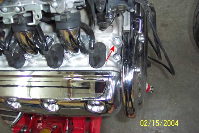
View of the air feed pipe going to exhaust port 3 under the engine on the right hand side.
Note: After removal, I have used a small aluminum
plate and a gasket (shown in the Parts Required above).
Others choose to cut off the end, fill it with JB Weld, and wait until
the next day before reinstalling with a gasket.

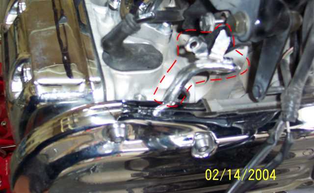
Removal of the crashbar makes it much easier to get at the front tubes.

The first air feed pipe is easy to remove after unfastening the shown bolt.
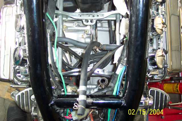
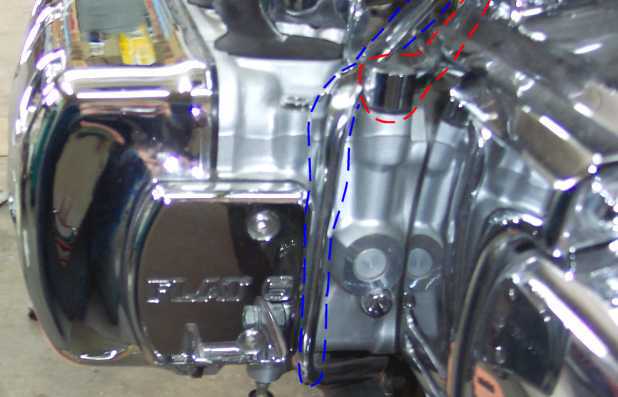
However the second air feed pipe, which passes
between the engine and the timing cover to go under the engine, requires
more effort.
Cut the pipe at the shown location with a pair of cutters and then remove
the top portion of the pipe.
After making another cut on the same pipe under the engine , it is possible to pull this portion up as shown in the pic. The portion of the air feed pipe which is bolted under the engine can now be unfastened and removed.
Some guys have simply cut the pipe ends off,
filled them with JB Weld and then let them sit overnight before reinstalling.
It makes for a clean set up.
I have chosen to use freeze plugs because
they are inexpensive (approximately .25 cents each), easy to install and
well hidden under the Kury spark plug valences.
To tap in the freeze plugs, use a 6 mm or 7 mm socket and a 1/4 inch extension
(because an 8 mm socket will get stuck in the freeze plug when it shrinks).
The installed rear plug on the right side is shown in the pic.

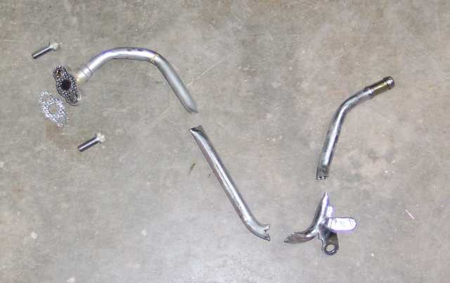
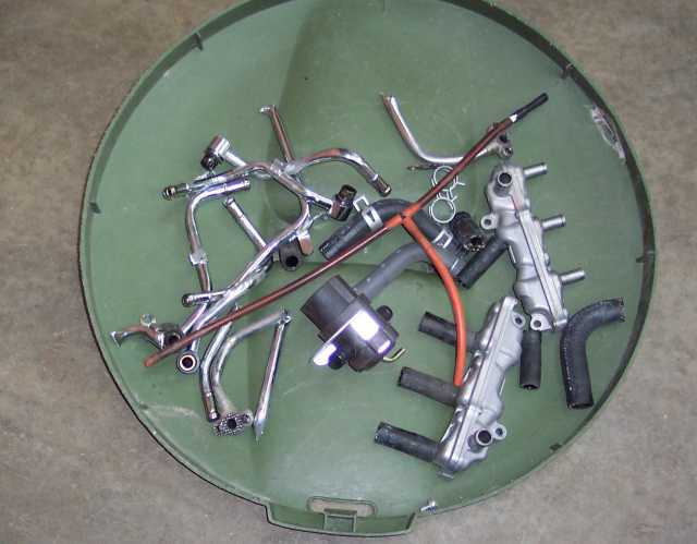
Removed Parts:
A PAIR control valve assembly, 2 PAIR check valves, vacuum tubing for the PAIR valve, 6 metal air feed pipes, rubber tubing.
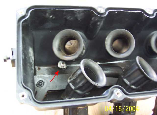
Inside the Airbox
The secondary air intake port (for the PAIR control valve) in the airbox must be plugged. After filling the hole with silicon, a bolt and nut with washers on each end did the job.
Under the Airbox
The secondary air intake port be plugged is the second outlet from the rear.
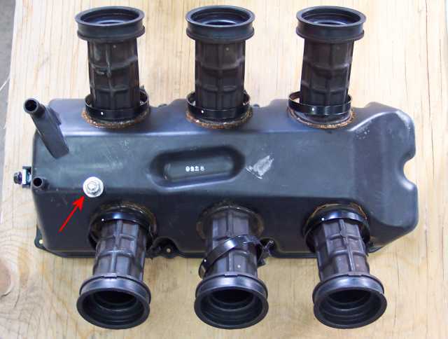
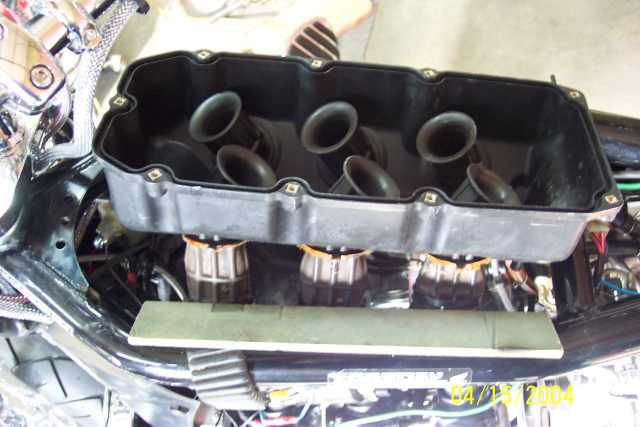
As can be seen in the previous pic, the six
intake tubes at the bottom of the airbox are splayed too wide to be easily
inserted within the two frame rails.
To ease installation of the air box, a wooden ruler can be used.
Tilt the airbox sideways in order to place all three large intake tubes
of one side against the inside portion of the frame rail on that side.
Place the wooden ruler against the three intake tubes on the other side
of the airbox and push them towards the middle until it is possible to
push the airbox down between the frame rails.
Voilà! You are ready to fasten the airbox, etc.